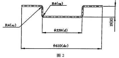
Stamping process and die design of 200L closed steel barrel bottom and cover Huang Zongwen Abstract: The 200L closed steel barrel bottom and cover are used as the object, and the stamping process and stamping process calculation are discussed. In the process calculation, the “query†function of CAXA wire cutting V2 CAD application software is used to effectively carry out the punching. The calculation of cutting force, tensile force, punching pressure center and tensile pressure center. Finally, the structural analysis of the blanking, drawing forming and flanging composite mold of the part was also carried out, and the CAXA wire cutting V2 was discussed. Application in the processing of mold parts. 1 Process analysis Figure 1 shows a 200L closed steel drum bottom and cover parts. The material is 08 steel. The thickness of the sheet is t=1mm. After forming, the surface of the part is required to be free of wrinkles, no deformation, no obvious tensile marks, and the thickness of the rounded joint changes. Small, and to ensure that the dimensions are within tolerance, the production volume is large. After analysis, the relative thickness of the blank is small, the amount of stretching is not large, the requirements for the flange are low, and the precision of the whole part is not high. The direct stamping can be satisfied. Therefore, it is decided to use the crank press to process: the blanking process is: blanking , stretching, flanging once formed. 2 stamping process calculation 2.1 Determination of the unfolding size of the blank The bottom and cover parts are rotating body parts, and the calculation of the unfolding size of the blank is divided into two parts. First, the expanded size of the stretch forming part is calculated (Fig. 2), and then the unfolded size of the flange is calculated (Fig. 3), and then the two are added. This is the unfolded size of the blank. (1) Stretching part expansion size calculation: =637.13mm (2) Flanging part expansion size calculation: Approximate calculation method due to the small size of the flanging portion (3) Blank expansion size calculation: D blank = D1 + 2L = 637.13 + 14.14 = 651.27mm Rounding = 651mm 2.2 Determination of punching force and punching pressure center (1) Punching force formula: Where: K - coefficient, usually K = 1. 3 t——Sheet thickness mm ?——The shear strength of the punching material is MPa, the checklist is: ?= 255~353MPa L - the total circumference of the outer contour If the outer contour of the part is irregular, it is more complicated to calculate L by hand. Here, the "query" function provided by CAXA wire cutting V2 is introduced, and the contour circumference can be conveniently obtained. The specific method is to use the drawing tool menu to expand the drawing. The outline is constructed, and then click the query menu, select the information to be queried, such as "area", "circumference", "center of gravity", "distance", etc., here select the query "circumference", then click on the outer contour line, Press the Enter key to find the perimeter size is 2045.18 (mm) Then P1 = 1. 3 × 2045.18 × 1 × 353 = 938. 53kN Considering the influence of factors such as material force, the blanking process should be at least 1000kN (100t) or more. (2) Determination of the punching pressure center The pressure center is the action point of the combined force of the punching force, which coincides with the center of gravity of the contour line, so the center of gravity coordinate can still be queried by applying the above query information of the CAXA line cutting V2. However, the area formed by this time is different. It is necessary to offset each contour line by 1mm at the same time, and then perform the center of gravity query on these areas to obtain the coordinates of the center of gravity. For the convenience of reading, the user coordinate system should be first used. Move from the origin to a datum point on the punch. Here, since the bottom of the bucket and the cover are symmetrical shaped parts, the center of the punching pressure is located at the geometric center of its contour pattern. 2. 3 Determination of tensile force and tensile pressure center (1) Tensile force formula: P2= KLt?b Where: K - correction factor t——Sheet thickness mm ?b —— tensile strength MPa of the material, check the table: ?b= 324~441MPa L —— the outer contour length of the part L value is still queried by the method described above to obtain L=1759. 29mm Then P2 = 0. 4 × 1759. 29 × 1 × 441 = 310. 34kN Considering the influence of the blanking force and the flanging force, the stretching process is at least 400kN (40t) punching, which is completed by the combination of punching, drawing and burring, although the punching and drawing are not the same. At the moment, but from the safety point of view, and analysis of the calculation results, it is considered reasonable to choose a 160t punch. (2) Determination of the tensile pressure center The method is similar to the method of determining the punching pressure center, and will not be described here. 2.4 Verify the processability of one stretch and the possibility of blank wrinkling (1) One-time stretch forming conditions among them: H/d - the relative height of the part H1/d - the maximum relative height of the first stretch (available in the table) Due to the relative height of the workpiece H / d = 19 / 560 = 0.034 < 0.45 The one-shot forming condition is satisfied, and therefore, the stamping process of the above analysis is correct. (2) Blank wrinkle conditions: t/D≥0.45(1-m) among them: t/D - relative thickness of the part m - stretch factor From the formula of the elongation coefficient: m=d/D=559/651=0.86 Then 0. 45(1- m) = 0. 45×(1- 0. 86) = 0.063 The relative thickness of the blank is t/D=1/651=0.0015 Since 0. 0015 < 0.063, the blank is not wrinkled, so the presser must be used in the design of the drawing die. 3 Design and commissioning of blanking, drawing forming and flanged composite die 3.1 mold structure analysis Figure 4 shows the structure of the blanking, stretch forming and flanged composite mold. The mold works on the JC31-160A closed crank press. Due to the large size of the mold, it is close to the press table size of 800×800mm. Moreover, cold-rolled strip with a sheet width of 660 mm is used as the billet production, and the blank feeding and waste discharging space is relatively small. Therefore, for the convenience of production, an open non-oriented die structure is adopted. Due to the large contact size of the scrap with the upper mold during blanking, and the movement of the scrap above the upper mold during stretching, a reliable working pusher is used, which can be realized by the connection of the discharge ring and the punch discharge lever. The JC31-160A closed crank press we selected has a pneumatic device. The air cushion pressing force and the ejection force are both 160kN, and the air cushion stroke is 80mm. Therefore, the crimping device adopts a better air cushion type, and the design pressure is designed. The side device has both the function of crimping and demolding. The blanking force is mainly guaranteed by the cushion pressure. The release force is mainly guaranteed by the spring force. The demolding of the tensile member in the upper die is carried out using a conventional elastic discharge device. Since the cross-sectional area of ​​the mold is large, the lower part is not provided with a backing plate, but is directly fastened with a screw or pressed with a pressing plate, and is embedded and positioned by a positioning pin. Due to the large mass of the upper mold base, it must be tightened by bolts, and the mold shank only plays a role here. For the positioning device of the blank, one side positioning is achieved by mounting on the punching table. 3.2 Stamping process 3.3 Analysis of wire cutting processing of convex and concave die-to-knife In the processing of the convex and concave molds of the pair of molds, since the processing size of the composite convex grooves is difficult to measure, the forming knife processing is used, which requires the tool template to control the outer dimensions of the tool after sharpening, so that the processed samples are accurate. , Small deformation, using WEDM. The key to wire cutting is programming. In the past, the traditional manual programming method was complicated and the accuracy was poor. Therefore, CAXA wire cutting V2 programming was adopted, which was fast and accurate, and the process of wire cutting can be demonstrated on a computer to verify Whether the line cutting track is accurate. The specific method steps are shown in Figure 5. First, use the drawing function to create the tool template pattern, and establish the cutting point S of the line cutting, then click the line cutting menu, select the track generation submenu, and input the offset of the molybdenum wire, according to the command prompt, pick up the contour to be processed. , the cutting track is generated, if the computer is connected with the wire cutting machine, the machining instruction can be issued on the computer, and the wire cutting machine tool is commanded to process according to the pattern by synchronously transmitting the program command. If the computer is not connected to the wire cutting machine, you can use the code generation menu to generate the code required for wire cutting (B code or G code can be generated), and can view and print it out, and manually input the machine tool to realize wire cutting. . 3. 4 mold debugging When debugging the mold, since there is no guide pillar positioning, the clearance is adjusted by the feeler gauge to adjust the gap between the convex and concave molds. The depth adjustment of the punch at the bottom dead center is adjusted by shallow to deep, multiple test methods, and manual cranking is adopted. The method is such that the press completes a stroke from the top dead center to the bottom dead center to check whether the punch is adjusted too deep to prevent the bump mold from colliding. Finally, it is necessary to adjust the blanking force. The adjustment method is to gradually adjust the air cushion pressure value from small to large, so that the blanking force is just right, and it is guaranteed that the drawing does not wrinkle and has no obvious pulling marks. Through debugging, when the pressure value is determined to be 0.5-0.6MPa, the bottom of the bucket and the cover are not deformed, and there is no wrinkle and no trace. 4 Conclusion 2018 New Products by Bossgoo itjt tkttt Bossgoo Wedding Company Co., Ltd. , https://www.bossgoodemo.com

![]()
![]()
![]()
P1= KLt?( N) ![]()
Check here: h1/d=0.45 
As shown in FIG. 4, when the upper mold moves downward, the blank is first blanked and blanked, and then the upper mold continues to move downward to stretch the bottom cover of the bucket. At this time, the spring 13 is compressed by the blanking plate 11, In order to ensure the balance of the blanking force, under the action of the balance force of the cylinder, the presser base plate 2 is pushed, and the force is transmitted to the spring 13 and then transmitted to the blanking plate 11 to achieve the balance of the force. When the stretching reaches a certain depth, the burring process is completed at the same time, and at the same time, the punching reaches the bottom dead center. Due to the continued rotation of the crankshaft, the upper mold begins to move upward. At this time, under the action of the spring force, the bottom cover of the bucket is separated from the tensile punch 14, and the discharge plate 5 pushes the waste away under the action of the punching lever of the punching machine. The mold, due to the action of the rubber 8, the bottom cover of the barrel is pushed away from the inner cavity of the punch 6, completing the entire stamping process. 